Hack IPCAM [ Anyka ] – Framebuffer SSD1306 Driver

Just an experiment to add the OLED Display and it can be accessed through a framebuffer driver.

Oled 0.96 I2c 128×64 SSD1306

Adapted from:

https://github.com/mkschreder/hack-ssd1306-openwrt

First follow the steps on how to prepare the environment to compile the drivers for Anyka

For the lazy, pre-compiled version:
https://github.com/ricardojlrufino/anyka_v380ipcam_experiments/tree/master/kernel/i2c_ssd1306_fb/ko_build

Copy driver src folder from:

anyka_v380ipcam_experiments/tree/master/kernel/i2c_ssd1306_fb/ssd1306fb

To: (anyka-src)/src/kernel/drivers/i2c/busses

Include new driver in Kernel changing this files:

If you have doubts, read this post that explains how to add new items in the kernel.
https://stackoverflow.com/a/19680541/955857

Enable new drivers:

Run: anyka/build/anyka_build.sh (it will call menuconfig)

Install drivers

insmod fb.ko
insmod fb_sys_fops.ko
insmod cfbcopyarea.ko  
insmod cfbimgblt.ko     
insmod syscopyarea.ko  
insmod sysimgblt.ko
insmod sysfillrect.ko  
insmod cfbfillrect.ko             
// insmod vfb.ko
insmod ssd1306fb.ko  

Active new i2c Device

echo "ssd1306fb 0x3c" > /sys/bus/i2c/devices/i2c-1/new_device

Check FB device

/mnt/sdcard/CAM/scripts # ls /dev/fb*
/dev/fb0

Demo C+ to write to Framebuffer

https://github.com/ricardojlrufino/anyka_v380ipcam_experiments/tree/master/apps/ak_test_framebuffer

Nothing too amazing, help improve this example!!

The i2c interface is very slow.

Hack IPCAM [ Anyka ] – OLED Display on CAM

How about adding an i2c display to an IP camera?
Yes, I myself was surprised to have made it.

Thanks to previous reverse engineering work and the compilation of an i2c Driver that miraculously worked, it is possible to utilize I2C devices using the native Linux API
This is a series of tutorials, you can see the topic list here

The display I’m using is ssd1306, and thanks to a library made for raspberry, it worked beautifully for the Anyka platform

Wiring

You can see i2c connections in this tutorial

Check if device is responding

insmod /usr/modules/i2c-gpio.k

Cross Compiling a Lib

git clone https://github.com/lexus2k/ssd1306

First activate the “anyka_v380ipcam_experiments” toolchain

source ../../anyka_v380ipcam_experiments/toolchain/activate.sh
cd ssd1306/src
make -f Makefile.linux

This will generate: ssd1306/bld/libssd1306.a

I pre-compiled it, if you have problems you can usehttps://github.com/ricardojlrufino/anyka_v380ipcam_experiments/tree/master/build_libs/libssd1306

Demo Project

Source:

https://github.com/ricardojlrufino/anyka_v380ipcam_experiments/tree/master/apps/ak_test_display

Build using:

/apps/ak_test_display/build.sh

Ajust ‘LIBDISPLAY_PATH’ variable in build.sh

Another test

Another (not so functional) test of how to implement a framebuffer driver for the display,

Hack IPCAM [ Anyka ] – Add more GPIOs using i2C

Following our tutorial on how to enable I2C on the camera (please read first), in this tutorial we will see an easy way on how to add more GPIOs using IO Expander
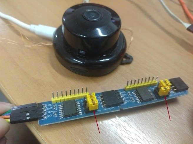
Wiring

The driver uses the PINS:
GPIO 7: label TX2, level 3.3v
GPIO 6: label RX2, level 3.3v

Using IO Expander I2C

A simple way to add more GPIOs is to use boards with PCF8574
This unique model is interesting because it is easy to cascade by connecting several in series.

Reference: https://www.youtube.com/watch?v=mXMkgQf3fqU

Using:

On buildroot precompiled version use this to load kernel driver:

insmod /usr/modules/i2c-gpio.k

Use i2cdetect -l to list the devices (drivers), and use the command : i2cdetect -y NUMBER, to scan i2C devices

Code Samples

TODO: ….

Hack IPCAM [ Anyka ] – Compiling I2C Software Kernel Driver

In this tutorial I will demonstrate how to 1. Compile a driver for Anyka camera and 2. how to implement i2C software and 3 using the example of IO Expander.

This is a series of tutorials, you can see the topic list here
Please note that I have already compiled this driver, and it is available in the BuildRoot version

Despite this being a market hardware, I ended up finding several GPIOs that can be used for general purpose, which makes it useful for developing some range of applications.

With the need to be able to have more IOs, I was looking for an alternative like maybe connecting an Arduino Nano and this being my GPIO “bridge”. This way it is also safer, avoiding burning the camera if you do something wrong.

As the camera has a second UART marked on the PCB (RX2, TX2), my first attempt was this. But I couldn’t compile a driver that enabled this function.

Doing a reverse engineering, I saw that there were some calls (insmod) for i2C drivers, but it wasn’t exactly for this camera model, because it doesn’t have motors.

These files exist in the original firmware:
./mvs/modules/ak_gpio_i2c.ko
./mvs/modules/akcamera.ko
./mvs/modules/aw_gpio_moto_driver.ko
./mvs/modules/ex_gpio_driver.ko
./mvs/modules/i2c-gpio-soft.ko

Also after several attempts to use the existing drivers, I couldn’t either. Even inserting the drivers, no new entries appear.

Ref: insmod /mvs/modules/ak_gpio_i2c.ko gpio_sda=7 gpio_scl=6 (not works !!!)

I ended up deciding to try to implement a virtual I2C driver (software).

The Kernel

The kernel used as a base to compile the modules is in this repository

https://github.com/grangerecords/anyka

Note that not all drivers are compatible, I had problems for example compiling the standard UART driver.
I believe the v380 camera kernel is slightly different from this one .

Keep this information in mind, when trying to compile other drivers, for example the UART one, I had this error.

insmod gpio_uart.ko
gpio_uart: Unknown symbol ak_timer_enable_sync (err 0)
gpio_uart: Unknown symbol ak_timer_request (err 0)
gpio_uart: Unknown symbol ak_timer_config (err 0)
insmod: can’t insert ‘gpio_uart.ko’: unknown symbol in module, or unknown parameter

Modifications to the build script.

I made some modifications to the build script, so as not to compile unnecessary things, you can use this file:

https://github.com/ricardojlrufino/anyka_v380ipcam_experiments/blob/master/kernel/anyka_build.sh

Put it in the folder: (grangerecords-anyka)/build

I2C Software Driver

To compile the driver we will apply a “patch”, and replace the file:

/src/kernel/drivers/i2c/busses/i2c-gpio.c

By this: https://github.com/ricardojlrufino/anyka_v380ipcam_experiments/blob/master/kernel/i2c_soft/i2c-gpio.c

Now, enable kernel module

Run: anyka/build/anyka_build.sh (it will call menuconfig)
Navigate: Device Drivers : I2C support > I2C Hardware Bus support
Check: GPIO-based bitbanging I2C

If all goes well, it will generate the file: anyka/output/kernel/drivers/i2c/busses/i2c-gpio.ko

Copy to SD card and run this command to initialize the driver:
insmod /mnt/sdcard/CAM/scripts/i2c-gpio.k

On buildroot precompiled version use:

insmod /usr/modules/i2c-gpio.k

Run i2cdetect -l to list i2c devices

Use the command : i2cdetect -y NUMBER, to scan i2C devices

Using I2C / GPIO

In the next part we will see how to add more GPIOs to the camera using an i2c expander

Hack IPCAM [ Anyka ] – Cross-Compile NodeJS and call native code

In this tutorial I will give quick tips on how to compile NodeJS for ARMv5 architecture used in camera v380. And also how to call native code through javascript.

This is a series of tutorials, you can see the topic list here

First of all, node is already available in the rootfs version that I make available at:https://github.com/ricardojlrufino/anyka_v380ipcam_experiments

Compatibility

In the case as we are focused on a camera with an old architecture and kernel, I made several build attempts and got the following results:

node v0.10.38 – OK (working)
node v0.10.48 – OK (working)
node v0.11.1 – FAIL **
node v4.9.0 – compile (but Segmentation fault)
node v4.9.1 – compile (but Segmentation fault)
node v5.11.1 – FAIL
node v6.17.1 – FAIL
node v8.17.0 – FAIL
node v10.24.1 – FAIL

On node v0.11.1, v8 engine 3.18.0. Removed ARM support for VFP2.
https://github.com/nodejs/node/commit/9f682265d6631a29457abeb53827d01fa77493c8

Cross-Compiling

I prepared a script that does the whole process, from downloading, configuring the variables and compiling.

https://github.com/ricardojlrufino/anyka_v380ipcam_experiments/blob/master/nodejs/v0.10_arm/build.sh

Download repository, goto folder /nodejs/v0.10_arm , and run ./build.sh

This will create a folder called: node_install, and static binary in /bin/node

This binary can be copied to camera and run on camera without dependencies..

Limitations

Although it also has NPM it is not very functional, because the file system is read only, it takes a long time to run. So the package management I do manually, copying the node_modules on the PC to the SDCARD.

Some modules I wanted to use like ‘sqlite3’ use native integration (C++).
As modules generally use the N-API API, and this api was only introduced in Node v8, libraries that use this feature will not work.

Below I present an alternative to be able to call C++ code using NodeJs from old versions

Calling C++ code from Node using NAN

We are going to use this library: https://github.com/nodejs/nan

Despite it claiming that it supports node (0.8, 0.10, 0.12), I had to downgrade the version (“nan”: “2.10.0”) (https://github.com/nodejs/nan/issues/933)

In order for us to compile the libraries, we also need to compile Node v0.10.48 for the desktop.

I already did it, you can find it at:
https://github.com/ricardojlrufino/anyka_v380ipcam_experiments/tree/master/nodejs/v0.10_linux64

If you need compile, you only need execute normal build.

git clone –depth 1 https://github.com/nodejs/node -b v0.10.48 node
cd node
./configure –prefix=$(pwd)/install
make && make install

Compiling a node library that uses C++

In the folder ‘/nodejs/ex_node_nativelib‘ there is an example.
To compile, use the script: build.sh in the directory above

This will generate

Working With the Extension on camera

You can unpack this folder on camera, and execute:

$ node
> var NativeExtension = require('./')
undefined
> NativeExtension.aString()
'This is a thing.'
> NativeExtension.aBoolean()
false

Exemple using library:

I prepared another example that uses this library: /nodejs/ex_nativelib_demo

You can just copy to camera and run. Note that here I am making use of an extra package “bindings”, it is responsible for helping to load the native library

TODO

I’ll provide more examples later, how to use typescript, and automatically generate a file with the modules in just a single file.

So that’s it, we have a high-level language to speed up the development process and when you need to be able to integrate with native code.

References

https://ctrl-v.biz/en/blog/63-node-js-cross-compilation-for-socionext-development-board
https://chrislea.com/2018/08/20/cross-compiling-node-js-for-arm-on-ubuntu/
Hack IPCAM [ Anyka ] – Booting Custom Rootfs from SDCARD

Hack IPCAM [ Anyka ] – Booting Custom Rootfs from SDCARD

Here I will explain how to boot from the SD card without having to make any changes to the flash memory. The idea is to change parameters of the booloader (u-boot) of the camera to allow loading rootfs directly from the sdcard.

This is a series of tutorials, you can see the topic list here:
https://ricardojlrufino.wordpress.com/2022/02/14/hack-ipcam-anyka-teardown-and-root-access

You will need soldering skills and a serial adapter … (I hope you are a maker)

Most linux cameras have some serial port (RX, TX), labeled or not, where you can access the console terminal, where you can execute commands…

As soon as you turn on the camera (this is in question), the “first thing” to run is the bootloader (usually u-boot), it is responsible for loading the kernel, and passing parameters that can also control the way the linux boots.

It is possible to load the Kernel directly from the SDCARD, but I could not in this camera. I believe u-boot was not compiled with this support. So let’s content ourselves with passing parameters to the existing Kernel, to load a roofs (/) from the SD.

The camera I’m working on doesn’t have an Ethernet card, but it’s possible to load the Kernel and Roofs over network using TFTP…

Serial Connection

TIP: I’m using enameled copper wire, taken from a transformer. The advantage of using this wire is that soldering is more accurate and less prone to breaking contact pads (yes, this happened to me using other wires)

Preparing SDCARD

First you must partition the memory card, with two partitions: 1Gb ext3, and the rest as FAT32. You can use any tool for this.

In my case, I would leave the 1GB (roofs) as the second partition, as I already had files and I didn’t want to lose them…

The file system (rootfs) used in the camera is SquashFs, but when formatting you can choose ext3 for example.
To prepare rootfs we can backup the original partition, and unzip it or use a new and “cleaner” distribution.

Basically the commands you need
1. Generate squashfs file from rootfs folder
mksquashfs [FOLDER] root.sqsh

2. Burn image to SDCARD using DD
sudo dd if=root.sqsh of=/dev/DEVICE status=progress bs=1MB

# CAUTION: DD CAN DESTROY YOUR HDD, PLEASE CHECK DEVICE using lsblk

I prepared a new distribution without any Chinese programs that will be spying on you. And a script with make SquashFs file and send to SDCARD.

Clone: https://github.com/ricardojlrufino/anyka_v380ipcam_experiments

You can use file /rootfs_v1basic/root.sqsh , or use script: make_sd.sh to create new root and send to SDCARD (please change the DEVICE in make_sd.sh, i’m using partition2 )

Booting new system (changing u-boot settings)

Connect the serial adapter to the PC and use this command (on linux terminal) to open serial port:

screen /dev/ttyUSB0 115200

Now power IP Camera ….
If everything is ok you should see the screen below, quickly press any key to enter the u-boot terminal;

You can follow some tips how to do this connection in Windows from this vídeo, or use WSL

Now there are several commands that you can explore in u-boot. Write help end hit ENTER, it will show the list of available commands;

Another command is printenv, which will show all the environment variables. We are going to modify then in order to change the boot process. Note that all changes are temporary, and if you want to make them permanent you can use saveenv

printenv example

Now, shutdown the camera and plug SDCARD. Power again, and… quickly press any key to enter the u-boot terminal;

Execute two commands to set boot to “/dev/mmcblk0p2”.

setenv bootargs console=ttySAK0,115200n8 root=/dev/mmcblk0p2 rw rootwait rootfstype=squashfs init=/init mem=64M memsize=64M

run boot_normal

Now you can se this ? use login root , password: root

Configuring WiFi

Create file a in ROOT of sdcard FAT partition
/mnt/sdcard/wpa_supplicant.conf

ctrl_interface=/var/run/wpa_supplicant
update_config=1
device_type=0-00000000-0

network={
        ssid="app-name"
        psk="pass"
}

Change ssid and psk, save and run:

/usr/bin/start_wifi.sh

Check you ip using: ifconfig

Use: start_services.sh  
To start a ftpd and telnetd !

On you PC you can connect using: telnet IP

On your PC you can navigate in folder using ftp://IP

Done !! now you can start customizing rootfs

(Update) I preparing um new rootfs for IoT Development available in the BuildRoot version

Hack IPCAM [ Anyka ] – Teardown and Root Access

V380 IP Camera based on AK3918 SoC

In this series of posts I’m going to cover some techniques I used to hack a IP Camera and take full control of it, from root access, reverse engineering, remote debugging, compiling your own programs and having access to the GPIO and image sensor. How about running NodeJS ??, in the end, you will have a cheap linux device to be able to do whatever you want..

My goal is to be able to turn a camera into a low-cost IoT device that is easy to find in the market. Maybe in the end she even stops being a camera, who said she was born to be a camera? Hahaha

The great advantage of this hardware in my point of view, was the amount of usable GPIOs, a USB port (used by WiFi), and …. after a lot of headache I managed to access the raw image sensor…

[BR Disclaimer] Essa camera é facilmente encontrado no Mercado Livre e AliExpress por volta de (BRL – R$120 -150).

On this series tutorial i will show how to :

Using C++ programming, You can do in this camera:

  • Audio out
  • Audio In (PCM and MP3)
  • Camera Get Raw Image
  • Camera Encoding MPEG/H264 (NO at this time…)
  • GPIO (5 free to use)
  • USB (need remove wifi to use)

I share examples on git: https://github.com/ricardojlrufino/anyka_v380ipcam_experiments

Specs and resources

Specs and Infos

Some information raised after getting access to ROOT, you will share it before

Info Boot

Anyka Linux Kernel Version: 2.5.02
Booting Linux on physical CPU 0
Linux version 3.4.35 (ma@ma-PC) (gcc version 4.8.5 (anyka (gcc-4.8.5 + binutils-2.24 + ulcibc-0.9.33.2)(20170223)) ) #5 Wed Sep 18 15:36:19 CST 2019
CPU: ARM926EJ-S [41069265] revision 5 (ARMv5TEJ), cr=00053177
CPU: VIVT data cache, VIVT instruction cache
Machine: Cloud39E_AK3918E+H42_V1.0.2
Memory policy: ECC disabled, Data cache writeback
ANYKA CPU AK3918 (ID 0x20150200)

# SoC Datasheet:
http://monitor.espec.ws/files/700cafec77419c2d7705f376c974b8d0ff72_986.pdf

# cat /proc/cpuinfo

Processor : ARM926EJ-S rev 5 (v5l)
BogoMIPS : 199.06
Features : swp half fastmult edsp java
CPU implementer : 0x41
CPU architecture: 5TEJ
CPU variant : 0x0
CPU part : 0x926
CPU revision : 5

Hardware : Cloud39E_AK3918E+H42_V1.0.2
Revision : 0000
Serial : 0000000000000000

# SoC Datasheet:

Clique para acessar o 700cafec77419c2d7705f376c974b8d0ff72_986.pdf

Flash Partitions (cat /proc/mtd)

chip: XMC QH64AHIG XM25QH64AHIG (Replaced by W25q64bv)

dev: size erasesize name
mtd0: 01000000 00001000 "spi0.0"
mtd1: 00180000 00001000 "KERNEL"
mtd2: 00001000 00001000 "MAC"
mtd3: 00001000 00001000 "ENV"
mtd4: 00180000 00001000 "A"
mtd5: 00199000 00001000 "B"
mtd6: 00133000 00001000 "C"
mtd7: 00073000 00001000 "D"
mtd8: 00180000 00001000 "E

Loaded Kernel modules (lsmod)

ak_sar_adc_drv 2325 1 - Live 0xbf152000 (O)
atbm603x_wifi_HT20_usb 476736 0 - Live 0xbf0cb000 (O)
otg_hs 13794 0 - Live 0xbf0c3000
ak_info_dump 1227 0 - Live 0xbf030000
akcamera 14324 3 ak_info_dump, Live 0xbf028000
sensor_sc1245 4813 0 - Live 0xbf023000
sensor_gc1054 3919 0 - Live 0xbf01f000
sensor_gc1034 3813 0 - Live 0xbf01b000
sensor_sc1235 3880 0 - Live 0xbf017000
sensor_sc2232 4145 0 - Live 0xbf012000
sensor_sc1145 4538 0 - Live 0xbf00d000
sensor_sc1135 4489 0 - Live 0xbf008000

Teardown

Look inside
FRONT
Front with labels

As you can see the serial is easy to find. I advise you to be careful when soldering, as the pads are easily damaged.

SoC

# SoC Datasheet:
http://monitor.espec.ws/files/700cafec77419c2d7705f376c974b8d0ff72_986.pdf

BACK (LENS REMOVED)

Root

give me the power !

There are multiple ways from getting root access from cameras
Examples:

  • Using defaults passwords (or luck)
  • DUMP Flash and unpack roofs, change password, repack and flash
  • Use the camera’s own update mechanism.
  • Boot you system from SD card or network (TFTP)

Here, a will explain two techniques.

Firstly thanks to the work of another developer, who reverse-engineered the original camera update system. It is possible to generate patches that run shell script, and patches to update the flash partition.

It is important that you read the original article, here I will only give my simplification of the scripts I created

https://blog.caller.xyz/v380-ipcam-firmware-patching/

I’ve simplified the scripts so that the patch applied will run the ‘run.sh’ script from the sdcard directly, without making any changes to the system.

I created a script that will do every step of preparing the files for the sdcard.

Clone repository : https://github.com/ricardojlrufino/anyka_v380ipcam_experiments

And in the ‘/patch_telnet‘, open script make.sh , change IPCAM_MODEL (see original article)

https://github.com/ricardojlrufino/anyka_v380ipcam_experiments/blob/master/patch_telnet/make.sh

Next execute ‘make.sh‘ script, the patch will be generated and moved to correct folder.
Then copy the files from the /COPY_TO_SD folder to the root of the sdcard

Put sdcard into camera, you should hear some messages that the patch is being applied

The ‘run.sh’ script will start telnet as ‘root’… and you will be able to login without asking for a password.
From you PC connect using: telnet 192.168.XX.XX

Now the power is yours…

Making permanent changes.

The rootfs is ready-only, you can not edit password, you need generate a patch to do this.

The ROOTFS patch is well explained in the original article, what I can add is some tips

Remember that it is possible to create a script that performs the backup of the rootfs partition. So that you can change the root password and generate a new rootfs patch. That way you can make permanent changes to the original system, so be careful.

TIP: Generate root password using (MD5):

openssl passwd -1

TIP: Script to backup all partitions (you can use in run.sh)

#!/bin/sh
echo "XXXXXXXXXXXXXXX BACKUP /proc/mtd XXXXXXXXXXXX"
cat /proc/mtd

BACKUP_DIR="/mnt/sdcard"

cat /proc/mtd | tail -n+2 | while read; do
    MTD_DEV=$(echo ${REPLY} | cut -f1 -d:)
    MTD_NAME=$(echo ${REPLY} | cut -f2 -d\")
    echo "Backing up ${MTD_DEV} (${MTD_NAME})"
    # It's important that the remote command only prints the actual file
    # contents to stdout, otherwise our backup files will be corrupted. Other
    # info must be printed to stderr instead. Luckily, this is how the dd
    # command already behaves by default, so no additional flags are needed.
    dd if="/dev/${MTD_DEV}ro" > "${BACKUP_DIR}/${MTD_DEV}_${MTD_NAME}.backup" || die "dd ${MTD_DEV}ro failed, aborting..."
done

Booting rootfs from SDCARD

the hacker way….

PLEASE CONTINUE READING IN NEXT

Esp8266 RF Bridge (EspHome)

Este é um guia básico de como utilizar um ESP8266 como Sensor de RF no Home Assistant, criando assim um RFBridge.

O sensor utilizado para receber RF 433Mhz : MRF-01 JFL
OBS: Outros sensores para Arduino podem ser utilizados (veja)

modulo receptor mrf-01 jfl central de alarme monitorado
Disponível no Mercado Livre

Para envio dos dados, podemos por exemplo usar um sensor/controle de mercado:

Os protocolos de RF compatíveis são:

  • HT6P20X
  • SC5262 / SC5272
  • HX2262 / HX2272
  • PT2262 / PT2272
  • EV1527 / RT1527 / FP1527 / HS1527

Não vai funcionar, se tiver usando um controle do tipo rolling code. Porque toda vez que você pressionar, ele vai enviar um sinal diferente (criptografado).

Você pode abrir o controle e verificar se ele tem algum chip com essas referências.

Iniciando

Primeiro você deve seguir o tutorial do ESPHome para fazer o flash do ESP:

https://esphome.io/guides/getting_started_command_line.html

Após tudo funcionando vamos seguir com os passos para adicionar o sensor.

Faça o download do repositório:

https://github.com/ricardojlrufino/esp_rfbridge/archive/master.zip

Altere o arquivo: esp-rf-bridge.yaml , mude as configurações de Wi-Fi e Senhas

Faça ligação do Sensor no ESP confirme a Imagem:

Segue um dica para uma montagem super compacta, usando Wemos D1:

Se precisar altere o pino no Arquivo: /433Sensor/RcSwitchSensor.h

Gravar o Firmware:
Execute esse comando no terminal:

esphome esp-rf-bridge.yaml run

Após uma gravação bem sucedida, você deve ver o IP do seu módulo no console, guarde ele pois vamos configurar ele no H.A:

Adicionando Integração (Home Assistant):

Se ainda não fez, vá em Configurações -> Integrações. Clique em Adicionar, e localize o ESPHome.

Se usa o HassIO pode ser um pouco diferente: https://esphome.io/guides/getting_started_hassio.html

Em seguida coloque o IP do Dispositivo:

Testando:

Pressione algum botão no seu Controle / Sensor 433Mhz e verifique se aparece no console os valores recebidos, como na imagem a seguir:

Adicionando Automação

No home assistant uma das maneiras de interagir com outros dispositivos é através da automação.

Vá em: Configurações > Automação , Clique em Adicionar.

Selecione:
Tipo de Gatilho: Estado
Entidade: Sensor.433Sensor
– No Valor ‘Para’, informe o valor correspondente ao seu botão

Em Seguida adicione uma ação:

Parabéns !!! Você criou seu primeiro RF Bridge para o Home Assistant

Exemplo com sensores de Abertura e Fechamento

Lembre-se, isso só é possível se o sensor for de abertura e fechamento, a maioria dos sensores são somente de abertura. Inviabilizando essa lógica.

binary_sensor:
  - platform: template
    sensors:
      janela_sala:
        friendly_name: Janela da Sala (status)
        device_class: window
        entity_id:
          - sensor.433sensor
        value_template: >-
          {% if is_state('sensor.433sensor', '58589508') %}
            True
          {% elif is_state('sensor.433sensor', '58589524') %}
            False
          {% else %}
            {{ is_state('binary_sensor.janela_sala', 'on') }}
          {% endif %}

Dispositivos testados

PS: Se conseguir testes com outros sensores e controles por favor compartilhe nos comentários para termos uma lista de componentes compatíveis.

Para verificar questões de alcance, bateria, performance, verifique no manual do dispositivo ou informações na internet.

Sensor Magnético Sem Fio Intruder Ecp 433,92mhz
FUNÇÃO: SOMENTE ABERTURA

Sensor Magnético Sem Fio Intelbras XAS 4010 Smart

OBS: só abertura e no modo ook

Sensor Magnético Sem Fio Digital SMW 210 Sulton
FUNÇÃO: ABERTURA e FECHAMENTO
MANUAL: http://sulton.com.br/wp-content/uploads/2017/05/SMW210-PDF.pdf

Veja no manual como colocar ele no modo de ABERTURA E FECHAMENTO.
Depois de ter configurado, ele vai começar enviar 1 código para abertura e outro código para fechamento

Sensor Magnético Sem Fio Digital Smw 150 Sulton 433,92mhz
FUNÇÃO: SOMENTE ABERTURA

Controle Rf433mhz De Parede -para Sonoff Rf/pro/pro R2

Sensor genérico

Sensor Presença Movimento Ivp Visory Rf Sem Fio 433mhz Ecp F105548 Original Saw Frequencia Estvável

Link:

https://produto.mercadolivre.com.br/MLB-1299077602-sensor-presenca-movimento-ivp-visory-rf-sem-fio-433mhz-ecp-f105548-original-saw-frequencia-estvavel-_JM

Observações Importantes:

https://www.youtube.com/watch?v=tVRkFnRTVoY

Sensor Infravermelho Alarme Sem Fio Intelbras Ivp 2000 Sf

Sonoff Rm433 8 Teclas Multipurpose Controle Remoto

Controle remoto genérico

Intelbras XAC 4000